
Updated 14 June 1999.
In the past whenever something had to be lighted, we have used yellow LEDs(Light Emitting Diodes),
as a substitute for white light. But now white LEDs are available. We can finally get rid of those
pesky yellows.
Unfortunately the new LEDs are not 100% white ! , they have a small blue shade, which is more
notably in pictures than in real life.
As a conclusion the white LEDs are far better than the yellow ones.
I have taken some pictures of these white LEDs in use, and I have to apologize for the sometimes bad quality.
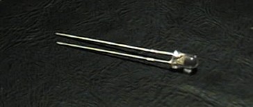 | |
| Another picture of the white LED | |
| Typical Voltage | 3,6 volt | Calculation of resistors : (Supplyvoltage - LED-voltage)/LED-current = Resistor Example : Supply-Voltage = 20 Volt ,LED-Voltage = 3Volt LED-Current = 20mA => (20V - 3V)/0,02A = 850 Ohm. Use 0,5-1 Watt resistors (the above uses 0.34 Watt) |
| Max. Voltage | 4 volt at 20 mA. | |
| Max. Current | 25 mA. | |
| Light Strength | max. 2000 mcd - Typical 400 mcd | |
| View Angle | 60 Degrees | |
| Life Span | 60.000 - 100.000 Hours (7-11 Years) | |
| Typical cost : | 5-7$ (will of course get cheaper in time) | |
So what can these new white LEDs be used for. Well they are very bright and can be used
for lamps, spotlights and other things.
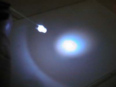
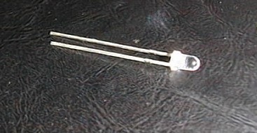
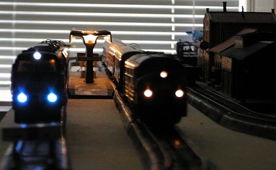
An example of the brightness of the LED : Here you can see the blueish light, but as I stated before its much more notably in pictures than in real life.
|
 |
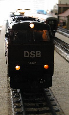
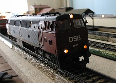
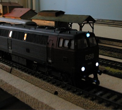
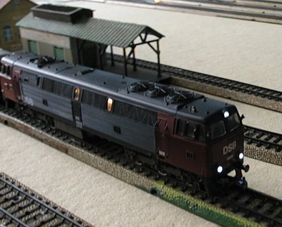
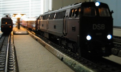
Here is what I have used the LEDs for.
The Spanish model railway manufacturer ELECTROTREN uses yellow LEDs as headlights for their
DSB MZ, and some of their other locs.
The yellow LEDs are on a small PCB, which are easy to remove. On the PCB there is 3 yellow
LEDs and 4 diodes. Pictures of the PCB can be seen here : Top-side - Bottom-side.
The schematic is as follows :
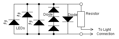
You now remove the 3 LEDs and the 3 normal diodes (the ones who are in series). I actually only
removed the outer 2 as the remainder is then left unconnected.
Now you place a zener diode instead of the normal diodes, and the white LEDs instead of the
yellow LEDs. It should be connected as this schematic describes :
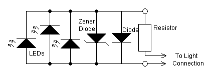
The finished result :
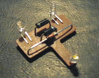
The value of zener diode and the resistor, can be changed, but I found a value of 470 Ohm/5W for the
resistor and 3,3 Volt for the zener to be OK. You can also put 4 or 5 normal diodes in series instead
of the standard 3 - but it may be hard to fit them.
I found it to be VERY important where you connect the resistor - (I actually blew the output transistors
of my Delta-Decoder).
The resistor should be connected to the "PCB-connector" on right side of the driving direction.
The resistors and their connection can be seen here.
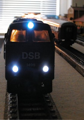
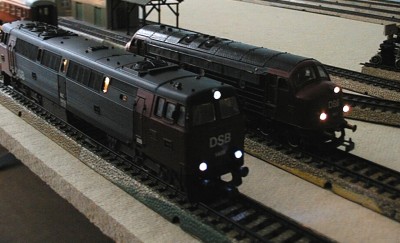
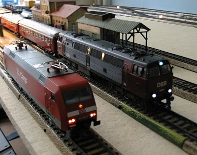
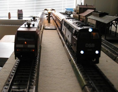
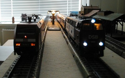
Here are some pictures to show the result. Again, be aware of the sometimes bad picture-quality,
and the fact that the light from the white LEDs looks more blue than they really are.
Please note the top white led. It is much more white than the others. This LED was the first I bought, - the others was bought one week later, and clearly they are another type which are much more blue. So if can look before you buy, you end up with a better result. | |